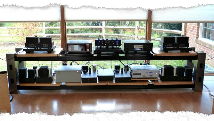
CREATING THE ULTIMATE 845 POWER AMPLIFIER
When I was in high school, I read an article in Audio Engineering Magazine titled,”The Musician's Amplifier.” The author talked about the challenges that he had to to overcome to complete the design, and about the legendary performance capability of its 845 output tube. He extolled the high power output capabilities of the 845 and its incredible sonic performance. This thing was a monster, and I was hooked. So like any audio fanatic I studied the 845's engineering ratings and marveled over its hyper-linear operating curves. This was in the early 1970s, when I was just beginning to study circuit design. Since I loved to think and dream, I decided right then that this tube should get serious consideration.
The 845 poses challenges for any designer. Because of its extraordinary sonic capabilities, it is very alluring. But in order to perform optimally, it requires a big and superbly designed, support system. A pair of 845 tubes set up to run in class AB1 has to be fed by a very large power supply that can deliver 1200 volts direct current, with good regulation. The tube has a very large voltage drive requirement, so in order to realize the highest power performance the associated audio circuitry has to be superbly crafted -- not to mention the design of the output transformer, which has to handle very high voltages and have great power bandwidth capability.
It was 1977 when I first listened to the 845. I installed it in a push-pull 211-based amplifier that I was using. Listening was joyful and exciting. I truly experienced the incredible resolution and flow of this grand tube! And even though the amplifier's power supplies and audio components were not ideal, the amplifier still reproduced my music with a new sense of detail and effortlessness. I lovingly worked with this amplifier for many years, installing more suitable output transformers, and improving its powers supplies and the drive circuits. But, because of the large size and great component cost, I tabled the idea of making it into a commercial design. Still, this was the beginning of the design process for the 845 amplifier shown above. The 845 had set the gold standard for me; yet I would not go back to designing with it for almost 20 years.
When I began doing professional design work, the 6336A/B became my tube of choice. I fell in love with this tube because it allowed me so much design flexibility, and it was such a joy to listen to. In listening tests, the tube displayed sonic capabilities that were similar to the 845, and because it used less power, the amplifiers I designed could be smaller and less cumbersome. In the 1980s, I worked extensively with the 6336B power tube, creating state of the art amplifiers that achieved very similar performance to that of my original 845 amplifier. And when I began using all tube-regulated high-voltage power supplies, my 6336B designs eclipsed it.
The final 6336B amplifier design, utilized two individually regulated power supplies, one for the front end and driver sections, and one for the output stage. The design also incorporated a regulated filament supply and wires, tubes, and transformers that were treated by cryogenic freezing. At its completion, I had mastered the art of tuning all of the related parts of an amplifier.
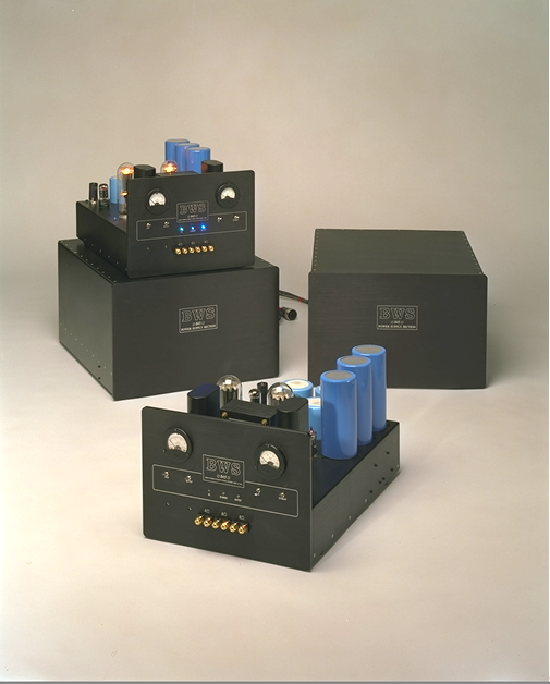
It was 1996, and I was ready for a new design challenge. From the beginning of my quest, I had wanted to design an amplifier that fully realized the performance of the 845 power tube, a design that utilized its great power output capability and highlighted its legendary sonic beauty. To accomplish this, I knew that I had to create a design that was an incorporation of many special ideas. The key task was to create a reliable output-stage power supply. I had to design a tube-based regulated power supply that would supply 1100-1200 vdc, at a constant duty of 200 ma and at a peak draw of 400 ma. My power supply designs for the 6336B amp had worked very well, but they only went up to 800 vdc. Hence, I had to design an even higher voltage supply that would not arc or suffer high voltage break down -- meaning that all of the parts had to have very high voltage ratings and had to be mounted and spaced out well off the ground plane of the chassis.
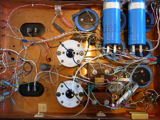
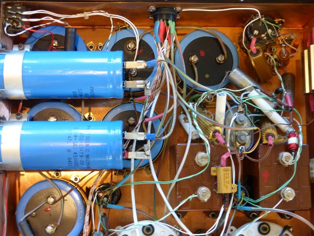
Since the power supply required such a high input voltage, I first worked out a way to maximize the efficiency of the high-voltage generator. I designed the head of the power supply using two 400ma power transformers, each of which is fitted with a full wave, solid-state, high-speed bridge-rectifier. These are then fed into two low loss chokes, which output into a four section, tube regulation circuit, controlled by a tube-based dc differential voltage amplifier. This design has worked well for many years now, and has proved reliable, and has had no voltage break downs. Achieving this was key for me, because with out it, I was not going to proceed with the design of the amplifier.
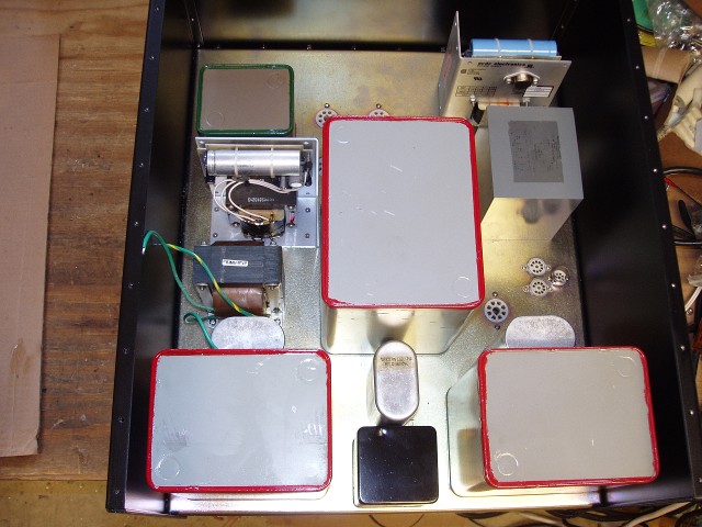
The production power supply module ended up weighing around 170 pounds. It is built on a very ridged steel chassis and includes this new plate supply, the driver supply that I designed for the 6336B amp, three individual filament supplies, and a negative bias supply.
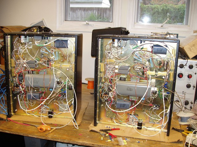
Next, I had to give a great deal of thought and consideration to the design of the audio amplification section, because I wanted to incorporate into it all of the new and different mechanical and electronic refinements I had created over the years. All of the individual components that I chose were mil-spec, and rated for high stress environments. The output transformer chosen was the Magnequest-built, Peerless 271A, which was originally used by Altec Lansing in their push-pull 845 amplifiers.
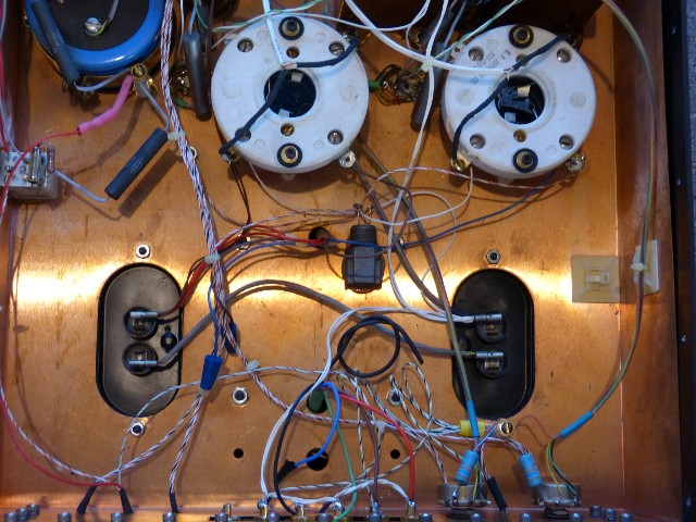
I constructed the audio section on a very rigid aluminum chassis, with a copper lining shield, which was all fastened using non magnetic stainless steel or brass hardware. I constructed all of the internal wiring layouts using point-to-point, individual wires and cables, which are cut to follow the shortest pathway possible. I made many of the the internal connections with terminal screw-downs, in order to minimized the number of solder joints. And, as a final enhancement, I sent the audio section to a lab which treated it by cryogenically freezing it, with the exception of the front plate and some of the large capacitors.
Tube type selection, for the front end and driver circuits, was done for high-speed and audio accuracy. The design uses an Amperex 6939 as the front end voltage amplifier. It drives two parallel RCA 6BL7s, which are utilized as the voltage amplifiers and phase splitter. These are then coupled to two parallel Bendix 6900 follower-driver tubes, which provide the drive for the push-pull 845s.
I am personally very grateful for all of the guidance that I received for this project. As a lover of music and audio engineering, it is an honor and a gift to experience this amazing amplifier. I consider this 845 amplifier to be a true reference standard of unparalleled quality. I first auditioned it in 1998, and I was utterly astounded by the levels of definition it revealed. Instrument resolution, size, placement, tone, and timber were just incredible. In my daily listening experiences, the amplifier authoritatively reproduces recording after recording, sonically illuminating its inner details, sound stage imaging, and musical realism. And so, my dreams are realized!